Another view of the ramp. Maybe you can see the cool tread pattern. No?
How about now?
Okay, you can definitely see the tread pattern here! I did it by cutting Evergreen scribed sheet. Some has grooves with .025" spacing and some .020" spacing. The finer spaced sheet I cut on an angle so the ends of the grooves would line up with the wider spaced grooves of the center strip.
Here's a view of the center bay which I modified to accept a scratchbuilt warp core I designed for this. Notice the landing gear bay is opened. It's too shallow to accept the feet, which I figure must fold together the way a book closes. The bays are getting scratchbuilt extensions to make them deep enough. It also makes a bigger canvas for detailing.
As promised, here's the warp core installed. It's a snug fit.
Another view of the underside, this time with the warp core and one landing gear.
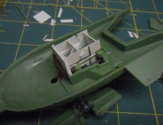
Here is a view of the built-up box that forms part of the deepened landing gear bays, made from .060" styrene. It's got some internal bracing for alignment and rigidity. Some of the plumbing is visible: it's made from paperclips and staples bent to shape.
Another view of the detailing.
Part 56 (the ramp, next to right) had a sinkhole because it's a thick part. I replaced it with the center section of part 42, which is the underside dome for the gear-up version. I just cut it out with a razor saw and proceeded to add an improved ramp.
Part 57 is this Y-shaped strut, two of which attach to the main struts. The instructions are vague about how to install it, and after some test-fitting, I realized there was no way to make it fit without bending. So I decided to come up with a replacement: brass wire and tubing, modified to resemble a hydraulic cylinder. I did test fitting and drilled holes in the hull so these will fit.
Next time, more of the same. Ho-hum!


BWAH!!!!
ReplyDeleteSuch Incredible detail!