I recently built Atlantis Models' repop of Aurora's 1/48th scale 8
inch howitzer. I thought it would be a walk down memory lane, as I thought I
remembered that about 50 years ago I built Aurora's Long Tom, which is the same
kit except for the gun tube. Now I think the kit I built back then was probably
Hasegawa's 1/72 Long Tom. Either kit is very play-worthy and fun for kids (and for modelers who can still remember being kids). One of these toys - I mean models (wink!) - can be just the thing to get the modeling mojo going again!
 The instructions tell you how to assemble the kit in travel mode,
but let you know when not to use cement so the play features all work. The upper carriage elevates and traverses, the
gun tube recoils, the breech opens (though it doesn't represent the breech
block at all accurately). The lower carriage has separate chock plates and
trail plates which can be stowed for travel or mounted for firing (more on this
below, since there are problems, mainly with the clarity of the instructions).
The split trails swing and can be joined to the limber plate and mounted on the
limber, and the lower carriage can be dropped out of the tandem wheel assembly
that supports it in travel mode (more on this below, as well). And of course,
the wheels all turn.
The instructions tell you how to assemble the kit in travel mode,
but let you know when not to use cement so the play features all work. The upper carriage elevates and traverses, the
gun tube recoils, the breech opens (though it doesn't represent the breech
block at all accurately). The lower carriage has separate chock plates and
trail plates which can be stowed for travel or mounted for firing (more on this
below, since there are problems, mainly with the clarity of the instructions).
The split trails swing and can be joined to the limber plate and mounted on the
limber, and the lower carriage can be dropped out of the tandem wheel assembly
that supports it in travel mode (more on this below, as well). And of course,
the wheels all turn.
 The kit
originally came out in 1958, and although it purported to be a WWII howitzer,
it's got features that were only seen later. Notably, the tires have gnarly off-road
tread, and I think the mount on the limber where the trails are attached is a
later version as well. So I decided that my howitzer lives in 1958. I painted
the figures so their uniforms are Olive Green, not Olive Drab – mostly. Old
stocks of Olive Drab were used up after the war, and from what I've read may
still have been in use in 1958. Boots were now polished black, and enlisted rank insignia were
no longer buff over blue. They look like olive green over blue, but I don't
know if Olive Green was the specified color. President Truman had integrated
the armed forces a decade before, so I painted the soldier holding the wrench to
be a black man. I chose to paint his uniform Olive Drab, to represent the old
stock being used up, though it's hard to see the difference.
The kit
originally came out in 1958, and although it purported to be a WWII howitzer,
it's got features that were only seen later. Notably, the tires have gnarly off-road
tread, and I think the mount on the limber where the trails are attached is a
later version as well. So I decided that my howitzer lives in 1958. I painted
the figures so their uniforms are Olive Green, not Olive Drab – mostly. Old
stocks of Olive Drab were used up after the war, and from what I've read may
still have been in use in 1958. Boots were now polished black, and enlisted rank insignia were
no longer buff over blue. They look like olive green over blue, but I don't
know if Olive Green was the specified color. President Truman had integrated
the armed forces a decade before, so I painted the soldier holding the wrench to
be a black man. I chose to paint his uniform Olive Drab, to represent the old
stock being used up, though it's hard to see the difference.
 The kit has some assembly problems, and
I'll refer to the parts by name since that's how they're listed in the
instructions. In Step 25, the springs are cemented to the forward and rear
tandem axles, but the mating surfaces are shaped differently: flat on the
springs but round on the axles. This means there is very little contact area.
This problem is exacerbated in Step 36, when the ends of the cross beam axle
are to be snapped into the holes in the springs on the tandem wheel assembly. The
snap fit requires a fairly tight tolerance for
the distance between the springs – too far apart, and the carriage just falls
out; too close together and it pries the springs apart, breaking them off the
axles. If I build another, I'll be sure to engineer the spring/tandem axle
assembly at the outset to get the springs firmly attached with the correct spacing.
The four small airbrake diaphragms (Steps 26 and 29) are also easily knocked
off when attaching the cross beam axle, and I'm not sure if there is any way
they can go on straight and not get in the way of the cross beam axle.
The kit has some assembly problems, and
I'll refer to the parts by name since that's how they're listed in the
instructions. In Step 25, the springs are cemented to the forward and rear
tandem axles, but the mating surfaces are shaped differently: flat on the
springs but round on the axles. This means there is very little contact area.
This problem is exacerbated in Step 36, when the ends of the cross beam axle
are to be snapped into the holes in the springs on the tandem wheel assembly. The
snap fit requires a fairly tight tolerance for
the distance between the springs – too far apart, and the carriage just falls
out; too close together and it pries the springs apart, breaking them off the
axles. If I build another, I'll be sure to engineer the spring/tandem axle
assembly at the outset to get the springs firmly attached with the correct spacing.
The four small airbrake diaphragms (Steps 26 and 29) are also easily knocked
off when attaching the cross beam axle, and I'm not sure if there is any way
they can go on straight and not get in the way of the cross beam axle.
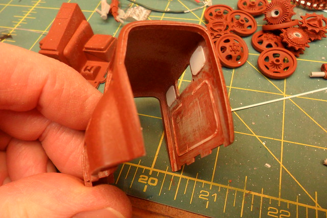
 Minor assembly problems occur with the trail ground support plates
and chock plates. The instructions don't give very clear indications on where
the former go when stowed (Step 40), and the inset photo of the completed
models shows them glued to the underside of the trails. Correctly assembled,
they slide into the trail plate hangers on the inside faces of the trails. Care
must be taken to attach the trail plate hangers properly in Step 33 so the
support plates will slide in and out. The notches in the lower gun carriage and
bottom plate to allow for the deployed chock plates need filing out, as you'll
find out when test fitting them. The instructions don't tell how to attach
these or the trail support plates when deployed for firing mode, but you can
see the notches on the underside of the carriage and the ends of the trails.
Both types of plates form a right angle with welded gussets on the inside of
the angle, and are deployed with the gussets facing forward so the recoil
doesn't pry the welds apart.
Minor assembly problems occur with the trail ground support plates
and chock plates. The instructions don't give very clear indications on where
the former go when stowed (Step 40), and the inset photo of the completed
models shows them glued to the underside of the trails. Correctly assembled,
they slide into the trail plate hangers on the inside faces of the trails. Care
must be taken to attach the trail plate hangers properly in Step 33 so the
support plates will slide in and out. The notches in the lower gun carriage and
bottom plate to allow for the deployed chock plates need filing out, as you'll
find out when test fitting them. The instructions don't tell how to attach
these or the trail support plates when deployed for firing mode, but you can
see the notches on the underside of the carriage and the ends of the trails.
Both types of plates form a right angle with welded gussets on the inside of
the angle, and are deployed with the gussets facing forward so the recoil
doesn't pry the welds apart.
 The sector gear (Step 9) is supposed to hold the upper carriage at
various angles of elevation, snapping over the stepped shaft (Step 13) as the
elevation angle is adjusted. This movement is very sensitive to any alignment error
in Step 9, so I found I had to file the sector gear teeth until it went between
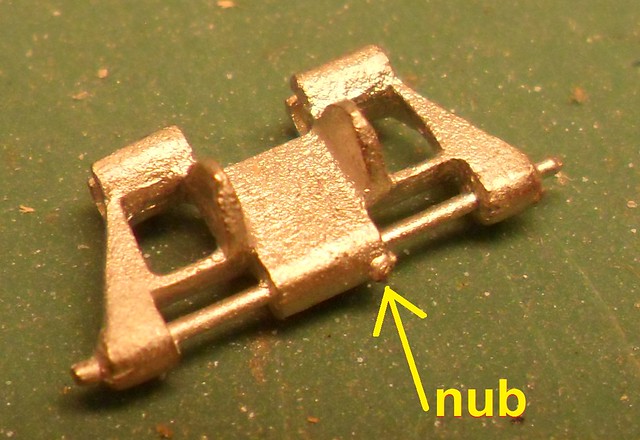
minimum and maximum elevation with a light click. Step 42 is also a little confusing
if you trust the photo in the instructions. The hitch lock should be oriented
as shown in the diagram.
The sector gear (Step 9) is supposed to hold the upper carriage at
various angles of elevation, snapping over the stepped shaft (Step 13) as the
elevation angle is adjusted. This movement is very sensitive to any alignment error
in Step 9, so I found I had to file the sector gear teeth until it went between
minimum and maximum elevation with a light click. Step 42 is also a little confusing
if you trust the photo in the instructions. The hitch lock should be oriented
as shown in the diagram.
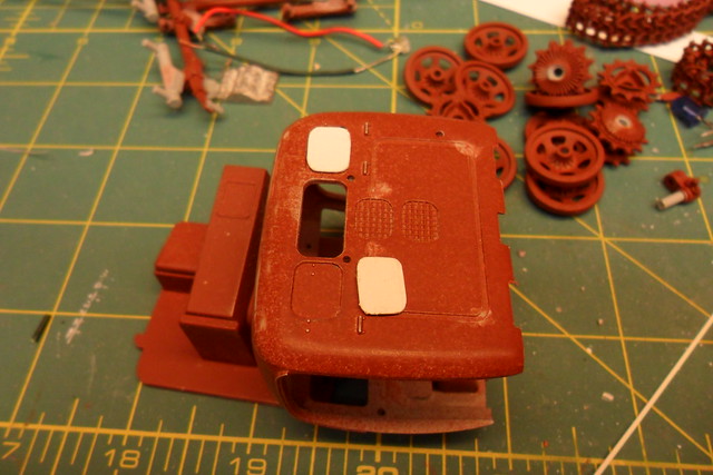
 Some filler is needed for the inevitable ejector pin marks and to
eliminate the seam in the assembled gun tube. Yes, kits of this vintage lack
slide molded barrels! Back in the good old days before slide molding, instead
of wailing and gnashing our teeth, we'd roll up our sleeves and we'd putty,
sand, and primer the gun tube for as many go-arounds as it took to get a smooth
barrel with a precisely centered round bore. So that's what I did, and frankly
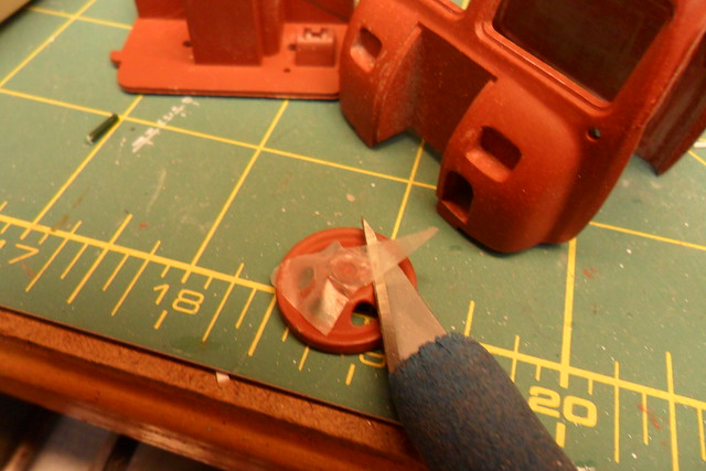
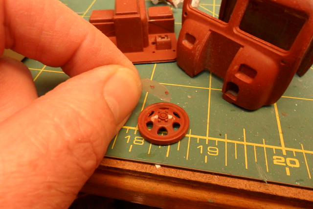
it wasn't that much trouble. The vinyl tires were the worst molded parts. All
the way around the tire was a weird hump across the tread, affecting some tires
more than others. It took a lot of sanding until none of the ten tires looked
noticeably like factory rejects.
Some filler is needed for the inevitable ejector pin marks and to
eliminate the seam in the assembled gun tube. Yes, kits of this vintage lack
slide molded barrels! Back in the good old days before slide molding, instead
of wailing and gnashing our teeth, we'd roll up our sleeves and we'd putty,
sand, and primer the gun tube for as many go-arounds as it took to get a smooth
barrel with a precisely centered round bore. So that's what I did, and frankly
it wasn't that much trouble. The vinyl tires were the worst molded parts. All
the way around the tire was a weird hump across the tread, affecting some tires
more than others. It took a lot of sanding until none of the ten tires looked
noticeably like factory rejects.
 Paint is mainly rattlecan Krylon camo olive with light weathering
except where the rubber literally meets the road, or the lack of a road (and
takes some with it). The decals are a new addition by Atlantis and appropriate
for postwar howitzers, and though I doubt they represent any actual markings,
pictures can be found of howitzers bearing stars, the words "U. S.
ARMY," and nicknames, all of which are on the decal sheet. It wasn't easy
to find room for them all, but I managed. They went down nicely over a coat of
Future and coated with MicroSol. I had no trouble keeping them from silvering
(some decals just seem to suck air in under them, so they'll silver no matter
what you do). They are not the thinnest decals and glossy to boot, but brushing
on some flat coat knocked down the gloss and all but completely hid the edge of
the carrier film.
Paint is mainly rattlecan Krylon camo olive with light weathering
except where the rubber literally meets the road, or the lack of a road (and
takes some with it). The decals are a new addition by Atlantis and appropriate
for postwar howitzers, and though I doubt they represent any actual markings,
pictures can be found of howitzers bearing stars, the words "U. S.
ARMY," and nicknames, all of which are on the decal sheet. It wasn't easy
to find room for them all, but I managed. They went down nicely over a coat of
Future and coated with MicroSol. I had no trouble keeping them from silvering
(some decals just seem to suck air in under them, so they'll silver no matter
what you do). They are not the thinnest decals and glossy to boot, but brushing
on some flat coat knocked down the gloss and all but completely hid the edge of
the carrier film.


I wanted to display the completed model on a simple diorama base to keep all the partsand figures together. I glued two seven by nine inch pieces of corrugated cardboard together with their corrugations at right angles to each other, clamped under the weight of a small anvil. The resulting base is very stiff. I applied MDF sawdust, brown spray paint, and Woodland Scenics foliage. To support the figures, I heated a straight pin and shoved it into one foot of each figure. After painting the figures, I cut the pins so only about 1/8" stuck out, then I stuck the figures to the diorama base like thumbtacks.