
If you followed the discussion on SSM forum about this, you know this has been a long time in the works. Pat Suwalski of
Tetryon Parts shared his progress as he worked to accurize the back side of the neck (aka battlehead) of the AMT 1:1400 Enterprise D, now re-released in clear styrene. He pointed out what was wrong with it and showed how he was fixing it to match the real thing--the large filming miniature. One problem was that the impulse engine was in the wrong place. However, this is not just about his correcting other people's mistakes, something everyone wants to do, but correcting his own, which few people want to do.
 |
| Old upgrade part test-fit. |
Finally, June 29 he offered the piece for sale. I ordered one immediately, in clear resin with matching decals (it's available in opaque resin as well, and decals are optional). I've got the clear kit, and plan to use the kit's aztec decals. The kit decals (
art by Jim Small of EIMB) are made to fit the kit, so if you correct an inaccuracy, you'll need a corrected decal as well!
It arrived in the mail July 17. I got out the 1701D kit and assembled the sides of the neck (parts 5 & 6) to test fit the replacement part. (Note: the part replaces the back of part 3, which is the back of the neck and top of the battle head, or the mating surface to the saucer section.) Pat had been candid in his posts on SSM forum (
here's the thread) about the fact that his part was thin and might warp. Well, it did. Mostly I think the part was squashed flat in the mail, since it was shipped in a padded envelope. The part has a boxlike structure on the inside of the impulse engine, and that was crushed, though it could be rebuilt easily with sheet styrene. The worst problem, though it was the most subtle, was a wavy distortion of the area where the neck blends to match the curve of the saucer, most pronounced above shuttlebay 2. I wasn't sure I could fix that as easily.
 |
| Old (top) and improved upgrade parts. |
 |
| New upgrade part test-fit. |
I emailed Pat immediately and he said he'd send a replacement part. Actually, I hadn't even asked for one, just asked about softening it in hot water to make it plastic enough to form back into shape. The new part arrived today (July 30), and comparing them side by side, you can see the new part has a deep curve to it and the old part is pretty flat. It's also twice as thick: according to my digital caliper, about .110-.120", as opposed to .550-.650" on the old one. The impulse engine box came through the mail okay, and I could see no wavy distortion in the part.I test fit the new part to the back of the neck, and found it was slightly flattened by its trip through the mail (it also came in a padded envelope), but to a much lesser degree, and that it conforms to the shape of the neck with a little finger pressure. I will put this part in hot water anyway, simply to soften it up so it won't want to spring back when bent. I more than suspect that Pat is working on this part or the packaging to eliminate even this little problem.
 |
| New upgrade part test-fit. |
So much for this peek at Tetryon Parts Enterprise D Upgrade. Sorry if you were expecting to see a build this time, but I look forward to building the clear Enterprise D in the near future, lit of course, and putting this part to good use, and there will be a series of WIP posts then.
And I can definitely recommend Tetryon Parts after this experience.
PS: July 31, 2012.
Now my part is perfect!
I dipped the part in boiling hot water for a minute, draped it over the other neck parts holding it in place with my fingers, then dipped the whole assembly into icewater. The clear resin is floppy like a sheet of rubber at 212 F. I'd recommend not getting the water that hot--maybe just the temperature of hot bathwater.
The flattening of the part wasn't too bad in the first place--it would have stayed in place with CA or epoxy--I just wanted to assemble it without putting any stress on it.


 Since the kit was previously finished, the old paint had to go. The paint stripper really looks like vomit, but has a very different nasty smell.
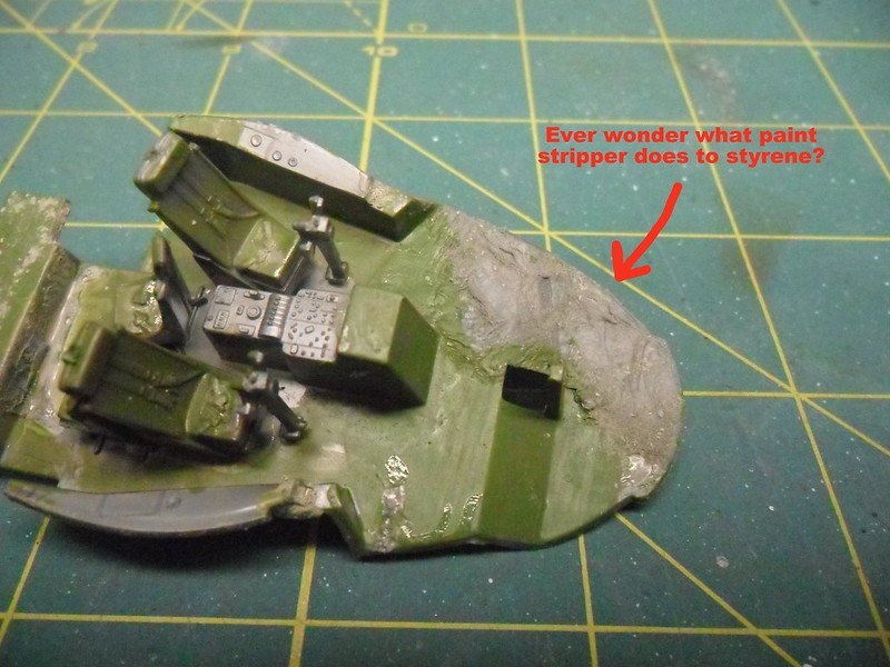
 Here's how it came out after soaking in stripper and scrubbing with a toothbrush dipped in lacquer thinner. Cleans up real nice. It was also possible to pop the nacelles off. I let the joint soak in acetone, then used a pair of slip-joint pliers and a piece of inner tube to pry off the nacelles without marring the surface.


 If you followed the discussion on SSM forum about this, you know this has been a long time in the works. Pat Suwalski of Tetryon Parts shared his progress as he worked to accurize the back side of the neck (aka battlehead) of the AMT 1:1400 Enterprise D, now re-released in clear styrene. He pointed out what was wrong with it and showed how he was fixing it to match the real thing--the large filming miniature. One problem was that the impulse engine was in the wrong place. However, this is not just about his correcting other people's mistakes, something everyone wants to do, but correcting his own, which few people want to do.


 Finished, as in I've had enough frustration and I've got other modeling projects I am impatient to get back to. That sounds disgruntled, but actually this was a pretty good learning experience. It was an impulsive mistake to paint the figures before bending them, and some of the paint came off. I had a little trouble bending the figures into the desired poses. In particular, the bend at the hips for a seated figure tended to come out too low. As a result, I have a better idea of how to get the bend to come out where I want it. Holding the figures with tweezers and dipping their feet in superglue worked pretty well, but I needed to be more patient about placing them. Amazingly, none of the ten figures were eaten by the carpet monster!
 Since last time, I decided I didn't like how the navigation/helm console in the kit part isn't undercut. (You may have noticed it's supported only in the center, so the ends hang out over the helmsman's and navigator's legs.) The captain's chair also needed to be undercut, as it sits on a swivel pedestal. It would have been easier to fix this right at the beginning, and it was very risky to do it now with all the added detail, but it seemed necessary. I hollowed out these parts using both a Dremel tool on its lowest speed with a #80 carbide bit, and various x-acto blades, then puttied it. The whole time I was looking at it through a jeweler's loupe that kept falling out of my eye socket. Luckily, the procedure didn't damage any of the added detail, and the shapes of the console and chair are somewhat more accurate now.
 Also, the main viewer and all the port side viewscreens were open holes, so I superglued bits of sheet styrene in back of them.


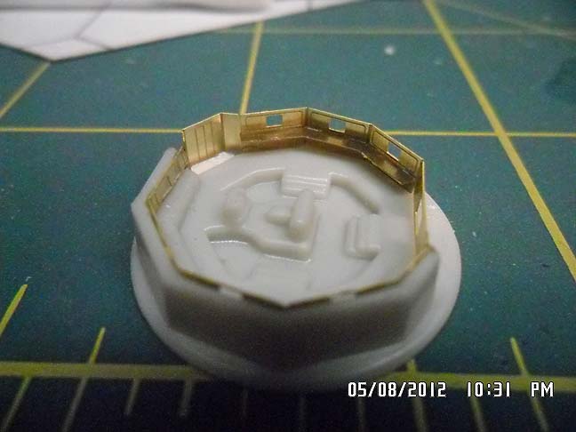


 This is what part 26 looks like on the tree, right next to the port nacelle. You can see there's a whole side missing. Maybe you can't tell, but the captain's chair and the navigation/helm console is there, in the center well. Pretty basic.