Showing posts with label WIP. Show all posts

Tuesday, January 21, 2014

RSO Part 4

Just a short update. I finished cleanup of the new vent holes to make them neatly geometrical, so they look like they were made by Germans (or Austrians, rather) and not cavemen. Then a shot of primer, and I added metal screen. The problem is that the cab is about a scale inch thick, but softskin vehicles like the RSO are made of sheet metal. The screen in the real thing is fastened over the opening from the inside and has no problem lying flat and nearly flush with the back of the cab. I couldn't come up with any better alternative than pressing the screen in from the inside, and the results aren't as good as I'd like. To really get the right look, one would need photoetched parts for the openings. Some plastic would have to be shaved off, the PE parts put in flush with the surrounding surface, then puttied smooth so it's impossible to tell where the PE starts. The screen would be attached to the PE from the inside, and would be nearly flush with the outside since the PE is so thin.

Although these screens don't satisfy me in this case, it was good experience and would look right for some applications. I'm leaving them be since there will be a canvas top, which will make them very hard to see. The duct inside the cab has several similar screens that will be more visible, so I will have to consider how to make those.

Sunday, January 19, 2014

RSO Part 3

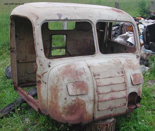
I noticed that while the vents on the rear of the model's cab are centered, the cooling air duct that fits in the cab is off-center. Aside from the fact the duct wouldn't line up with the vents, the vents are supposed to be off-center, as you can see in the picture. I forget where I found this picture, but apparently someone found this RSO cab somewhere in Poland.


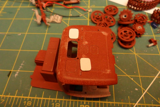
In the next picture, you see the relocated openings superimposed over the old vents, which are just surface detail. The lower opening shouldn't be as tall as the upper, so I corrected that, too. I have since started puttying over the old vent detail and mesh will go in the openings to complete the vents.

Aside from this, I've been puttying and sanding ad infinitum, primering, and opening the vent holes in the front of the cab. I found out those two rectangular covers with rounded corners that you see in the top picture are dampers for vents. Expecting the RSO to have headlights other than just the Notek blackout light, I had thought they were headlight covers. I even found a wartime photo of an RSO with what appeared to be light shining out one of those openings, but vents they are, and for a good reason. It could get hot in the cab sitting next to the air-cooled V8 engine. Wartime photos often show just one of the vents open, usually the driver's vent.

Sunday, January 5, 2014

RSO Part 2


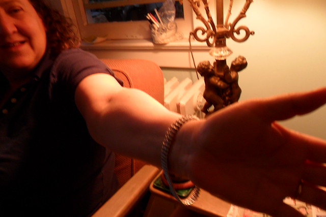
Friul should consider branching out. Check out the what a fine bracelet these RSO tracks make, modeled here by my lovely wife Ilene.


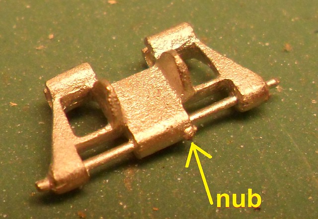
Closer inspection reveals why some of the pins broke after I assembled the first run of track. The nub you see in the photo at right is enough to wedge the adjoining link causing it to pull on the pin, shearing it off. Before assembling the second run I filed any nubs off.


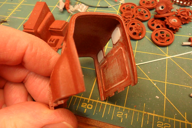
The shapes stamped into the back of the cab should also show on the inside, as in this close up from a walkaround at the Military Models website in New Zealand. I edited the picture to indicate the stamped shapes. This particular walkaround is great because the vehicle is painted white and partially disassembled, making details more visible.

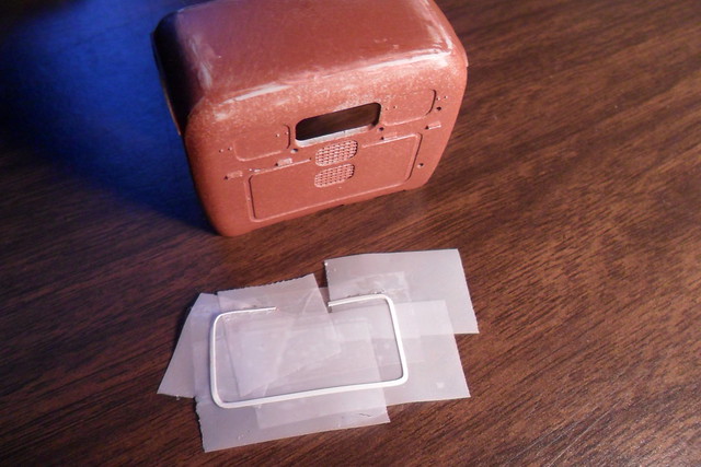
I made the matching raised areas in the back of the cab by fitting sheet styrene into the depressions. First I taped a piece of strip styrene into the depression running around the lower part. I bent the strip to get it to go around the corners.

Once I had the styrene shape formed, I simply peeled off the tape and the styrene with it.


Next I put it into the cab and cemented it in place, carefully peeling off the tape.


The rectangular depressions on either side of the rear window have sheet styrene cut to fit...


...which is then transferred to the inside to form the raised areas, then cemented in place.


I found in period pictures and modern day walkarounds that the main bolt holding each roadwheel on is often secured with a strap held on by two opposing lug nuts. The RSO probably came from the factory this way. I decided my RSO should have this feature.

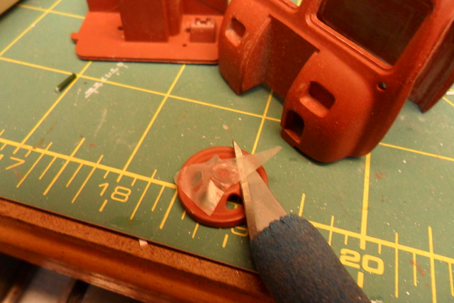
I wanted to simply put a strip of brass with two holes over the lug nuts, but this wasn't practical. My only other choice was to remove two lug nuts, superglue a strip of brass on, and reattach the lug nuts with superglue. To this end I sliced two lug nuts off each roadwheel with a fresh #11 blade (with tape over the nuts to keep them away from the carpet monster).

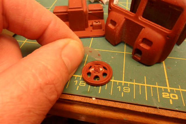
Then I pulled off the tape taking the two nuts with it. I shaved off the remaining plastic left behind so the brass strip would be tight against the wheel. Not shown is how I cut a strip of brass, pressed it over the hub of the wheel, and cut it to length. Some of the wheels got scored in the process, so a bit of putty was required to cover up the damage.

And here are all eight roadwheels modified with the brass strip and the lug nuts reattached. Comparing my work to photos of the RSO, I made the strips a little too wide, but I'm just glad the carpet monster didn't get any of the lug nuts. They are practically microscopic!

Wednesday, December 25, 2013

RSO, Part 1

Oh, by the way, Merry Christmas! It's a long time since I posted, having gotten derailed from modeling this summer and making very little progress on aztec decals for Starcraft's 1:1400 scale Saber-class starship. Meanwhile, I've started on an armor (well, softskin) project that should get me back on track (no pun intended) but not take terribly long to complete.

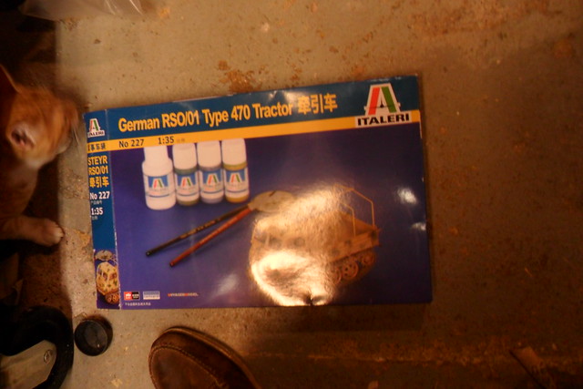
I recently got the Chinese version of Italeri's 1/35 RSO. It includes a sheet of photoetched details by Voyager and decals by Cartograph, neither of which I would expect to find in the Italian boxing. Sorry about the glare, but you know what the model looks like. The cat's name is Rory (as in Mr. Amy Pond). This kit was very inexpensive, Lucky Model's deal of the month or whatnot. A little history of this kit: Italeri (then Italaerei) bought the molds for this kit from Peerless/Max when they went out of business in the 1970s. Peerless Max is probably best known for their kits of various U.S. Army subjects in the range between the Jeep and the deuce-and-a-half (Italaerei bought a bunch of these molds, too). I never knew about their RSO since I don't remember seeing Peerless/Max kits at the 5 and dime where I bought models back then. But the Peerless/Max kits, while primitive by today's standards, are still pretty impressively detailed and engineered kits, and AFAIK pretty accurate.

A major reason I bought this kit was that I already had the Fruil tracks for it. Someone had tossed them into the table of parts for the Iron Modeler competition at Wonderfest. The stuff was free to all takers once the competition was concluded. Since I build armor also, I snatched these up.


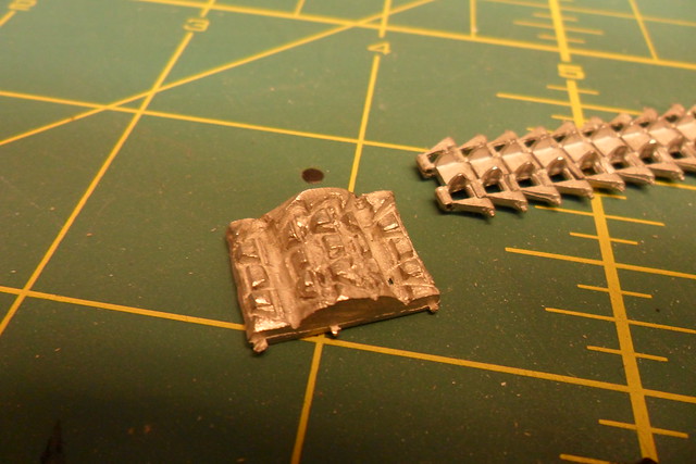
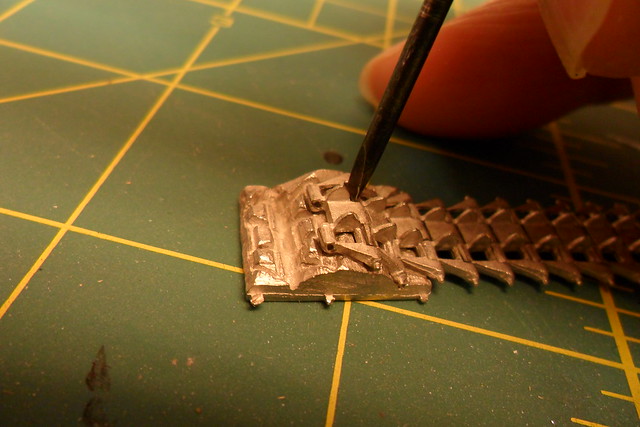
At right you see the assembly fixture, followed by a picture in which I demonstrate how to use the fixture. These tracks are not what I expected: there is no wire to form track pins. Instead, the track pins are cast as part of each link. The part of each link that is like a hinge barrel is open so it can trap the pin in the next link. You place the assembly on the fixture and press the open barrel shut (here I'm doing it with a jeweler's screwdriver), and you get workable track.

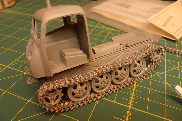
Here's one run of track test fitted on the tractor. They look pretty good here, but I had to cut out a couple links in which the pins broke, probably because I closed the links together with too much force. PMMS has a review of Fruil's track set for the RSO, but it's for a new version, which confusingly has the same number of ATL-29. The differences are that the new links are more accurate, that they have wire for link pins and bolt head parts to make right- and left-hand tracks, and that sprockets are included. The new set apparently takes 69 links per run. I don't have the Panzer Tracts for the RSO, so I don't know how many links it should take. I looked at the best photo I could find of a real RSO and tried to count the number of links, and it seemed to be 72. The run I assembled took 67 links.

Since there are two versions of Fruil's track set ATL-29, you may get the old set when you think you're ordering the new set. However, I'm pretty happy with the old set. They are a bit wider to fit the wider kit sprockets, but the difference in width is kind of hard to see. Once I got the hang of assembling them, it was a breeze. True, the bolt heads on the link pins aren't there, but to my eye these are too large on the new track set. All in all, I don't see a lot of reason to prefer the new set over the old.

Thursday, July 4, 2013

1/1400 Saber-class NCC-81623 USS Da Vinci

Here's the beginning of a new project I hope will be brief. I acquired a Starcraft 1/1400 scale Saber. It's one of the new starship classes seen in Star Trek: First Contact. In the Starfleet Corps of Engineers books, most of the action takes place on one of these ships, USS Da Vinci NCC-81623, which this model will represent.

EDIT (28Feb2014): I've heard from another modeler who used Klean Strip on resin and it ate into the resin. Like the advice given on a lot of products, test on an inconspicuous area to make sure it's safe. This product also works really fast, so you should not have to leave it on long.

Since the kit was previously finished, the old paint had to go. The paint stripper really looks like vomit, but has a very different nasty smell.


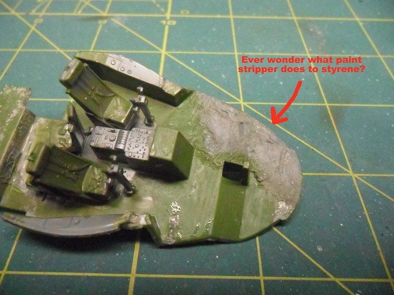
Incidentally, it was possible to use this stripper only because this model is resin. Out of scientific curiosity, I put some onto painted styrene. Here's the result:
It strips the paint, then turns the plastic into taffy. Back to the Saber...

Here's how it came out after soaking in stripper and scrubbing with a toothbrush dipped in lacquer thinner. Cleans up real nice. It was also possible to pop the nacelles off. I let the joint soak in acetone, then used a pair of slip-joint pliers and a piece of inner tube to pry off the nacelles without marring the surface.


It was bugging me that there are some symmetry problems with this kit. This is an older Starcraft kit and not quite state of the art any more. It was assembled just fine; in fact, there were locating pins for the nacelles. In this picture you can see where I had to sand down a panel that stuck out too far. Easy fix.
The starboard nacelle's pylon overlaps some lifeboats, and the port nacelle's front face is too far forward. Mostly this is an easy fix also, requiring just a bit of sanding. The mating surface to the pylon on the underside of the saucer, however, is a bit proud of the surface and needs to be carefully sanded to avoid wiping out the lifeboat detail. In fact, I had to re-establish some of this detail by scraping with an x-acto blade and using a scribing tool.
Here it is fixed. You can also see a dark stain on the underside of the saucer. Looking at it closely, I realized it's composed of paint that filled in thousands of tiny bubbles, and it won't be visible once it's primered. Another symmetry problem that needs to be addressed is the dogtooth detail on the leading edge of the saucer. A little bit of sanding will rectify this.


Next time: Primering and filling and sanding, oh my!


Monday, May 20, 2013

KBoP Part 21: Completed! And at Wonderfest 2013

There are more pictures of this model at Modelers Miniatures and Magic.

Here's a bit of video I shot at Wonderfest of the finished KBoP to show the lighting effects. Doesn't quite show all the lighting but I'll post more later. I was shocked when it won Gold in the Vehicles category and Best Round 2 Model Kit Adult Division. I knew darned well what things were wrong with this build--maybe they're minor but there are plenty of defects. I guess the fact that it's a Klingon ship let me get away with things that would be unacceptable on a Federation ship.

Halleluia! Blogger and YouTube are talking to each other again, so I can embed my video. It's always the kids who get hurt when the parents can't get along. Here's another short video showing all of the lighting effects. In Deutschland ist dieses Video möglich gesperrt wegen des Urheberrechts der Musik. Sie ist Beethovens Symphonie Nr. 7, zweiter Satz. (I really like Beethoven's Symphony No. 7, especially the second movement, and it sounds a lot better than what the video camera recorded: my breathing and air conditioner noise.)

Here's a longer video that shows all the lighting effects along with my boring narration where I explain the things I did with this model.


As I said, I'll take more pictures and video and add them to this blog post in the next few days. I actually finished this model on Saturday morning in my room at the Crowne Plaza upstairs from Wonderfest, and what photos I took were of other people's stuff.

Wednesday, May 15, 2013

KBoP Part 20

Quick update as I am frantically trying to get this done before leaving tomorrow to go to Wonderfest.
Here's the wings on. No disruptor cannons yet so it can't go "Pew, pew, pew!"


I have painted lots of KBoPs already. I don't need another one with red wings on the underside. Besides, that's a Romulan thing. Klingons' favorite color is green. Okay, red if it's spilling out of humans, but I mean ship colors.


The blank side of the landing gear doors will show, and Round 2 put nothing on them except ejector pin marks. So I hollowed them out a bit and added styrene detail before painting and weathering.

Tuesday, May 7, 2013

KBoP Part 19

I put the wings on. I notice a slight asymmetry in the fit, but at this point I'm not going to do anything about it. A side effect of installing lighting is it makes construction a real pain and correcting fit issues becomes more trouble than normal.
There are some kind of vent-looking things on either side of the top of the engine deck. The recessed detail looked a little plain, so I dressed it up with photoetched parts on both sides. (From the spares box--it's 1/700 ship ladders.)
Finally, all of the lighting is soldered together. Here I have one 9V battery powering all of the lighting at once, and hooray! everything still works. I have yet to route some of the fiber optic, then carefully close up the hull halves. Then all that's left to do on this bird is finish up the outside.

Sunday, April 28, 2013

KBoP Part 18

Last Sunday was Model Day with Jim Pugliese and Eric Longstreet of the Collective at Jim's house. Got a little done on it up to that point and that day, though most of it since last post has been electrical work and not much to look at. I've got the command pod closed up now, and no light leaks so far. The wires to supply electricity to the model come in through the two objects on the starboard side. See the second pic--hard to see because that part is in shadow, but if you know the Klingon Bird of Prey, then you know what I'm talking about. They seem like a likely function is power couplings when on the ground.

Unfortunately, after last Sunday I realized how close Wonderfest is--it's the weekend of May 18-19! Yikes! Between freaking out over that sudden realization and the fact that I had a gazillion other things to do, I got absolutely nothing done on it till this evening. And what I got done was ungluing the lower part of the command pod, which wasn't fitting right, reattaching it, and puttying the seam. But the closing up of the hull has commenced.

Also stopped by Steve Neill's hangout. This evening was the first time the hangout was in operation, and I guess it's a work in progress for everyone to figure out how this technology works. I participated as best I could with no mic or webcam, which is to say little at all, though I shared one of these pics. We'll see more of how it works on coming Sundays.

Sunday, April 7, 2013

KBoP Part 17


Studio model of Klingon Bird of Prey
Another mini-update.

Like I said, there needed to be more detail in other more visible parts of the ship, and one area that needed help was the shallow opening full of wiring or plumbing on the top rear of the command pod. At right, you see what I'm talking about on the real thing. I didn't attempt to recreate the studio model, but by the end you'll see what I did do to improve the detail on this area of the kit.


The kit detail is skimpy here, so I decided to cut it out and back up the hole with an insert loaded with detail.Cutting out the hole was pretty easy. As easy as Cortez burning his ships. No turning back now!


The plastic is pretty thick for the scale so I hogged out the surrounding area to make it look like a thin shell. I slopped on black paint in order to...


...transfer the impression of the opening to this sheet styrene backing. Actually, it's two layers cemented together. I held it in place to make it conform to the shape of the inside of the hull, and when it came out it was permanently formed into about the right shape.


Here's the blank styrene backing held in the opening.


I added wire, solder, and styrene shapes to fill in the area of the backing that would fit in the opening, painted it red-brown with a grimy black wash and dark yellow drybrushing.


Then installed it with 1-minute epoxy.


And here's the prize in the box. It's jazzed up with a bit of fiber optic lighting.

Saturday, April 6, 2013

KBoP Part 16

Another mini-update. The airlock chamber that exits through the top hatch in the forward hull is now installed. And populated. Er, Klingonated. There are two Klingons in there. In the first picture, there's a Klingon climbing the ladder. In the second, you can see another Klingon standing just inside the inner hatch. These are Tamiya 1/350 sailors (well, figures; the only thing that makes them sailors is that they are made to go with 1/350 ship models). I painted them to look like Klingons, which didn''t take much as they are two tenths of an inch tall, or 5mm. The guy on the ladder needed to be bent up a bit to get him to be in about the right pose.

You might also notice the floor texture in the top photo, and the light green color of the floor beyond the inner hatch in the lower photo. The texture is fine mesh superglued to a disk of styrene, and I chose the light color simply because otherwise you couldn't see a darn thing in there. Now it needs the hatch on top, the rest of the lighting installed, and the upper and lower hull halves to be glued together--with wires sticking out to connect to an external power supply.

Wednesday, April 3, 2013

KBoP Part 15

Just a quick update. I had an hour before bed to do some stuff I thought about to the airlock chamber under the hatch. It made sense for the interior door to have the same sort of control panel as the one at the top of the boarding ramp. So I made another one with 0.25mm fiber optic threaded through a tiny styrene polygon with holes drilled with a #80 bit. The control panel will connect to the same red, yellow, and green blinking LEDs as the other one. I also drilled out holes for lighting fixtures near the top of the chamber and threaded fiber optic through those, which will connect to warm white LEDs in the forward hull. I put it all together with 1-minute epoxy, plus a bit of styrene tubing to keep the control panel from wobbling. Then a bit of paint. It is going to be a pain to put this all together with fiber optic connecting parts in the top and bottom hull halves, but I will manage somehow.

Sunday, March 17, 2013

KBoP Part 13

Previously on Klingon Bird of Prey...

Here are some progress pics of the Klingon Bird of Prey. I did take a bit of a break from it--I never completely stopped but the work slowed down for a while. I'm nearly ready to close up the hull, stick on the wings, and do the finish work on it that you do after you already see the light at the end of the tunnel. Speaking of light, here's the red and amber lighting for the torpedo emitter (and navigational deflector?). Paint needs some touch-up.

 Here's the wiring for that lighting. I was originally going to add nine small red LEDs to light up the ring around the torpedo emitter, and had them all soldered up, but try as I might could not fit them in. So there are three ultra-bright red LEDs, plus the amber one in the middle. Plus limiting resistors so it can run on 9VDC. All packed in epoxy.

I used the technique promoted most famously by Don Matthys of Don's Light and Magic to glaze the windows in the lower front command hull, but used 5 minute epoxy, which is pretty viscous, so it didn't fill the windows completely. His method is to tape over the outside of the opening and pour in clear resin. Here I tried a variation on the technique: I cut out holes in the tape, painted in there (to repair damage to the paint job and to seal the tape better). Then I smeared in clear epoxy from the outside. It worked better but the result wasn't perfect.

I couldn't resist: The detail along the trailing edge of the wing sticks out on the kit, but on the filming model it's recessed. So I hogged out the detail and replaced it with strips of Evergreen corrugated siding. You can see the LEDs and fiber optic in there, too. The LEDs are those Christmas lights I mentioned before that consist of warm white SMTs on lacquered wire with a blob of clear resin on each one. I drilled out a hole in the resin for the 1mm fiber optic and inserted it with epoxy. Then sealed the light in for better transmission with repeated coats of Metallizer alumiinum plate and Future.


Here's the new trailing edge. Sorry about the focus. You get the idea.

Lastly, here's a lighting test. What are those things, headlights? Navigational deflectors? I don't know; maybe I'll have to get the owner's manual now that it's out.


Next time: maybe I'll get the last of the lighting installed and close it up.