Sunday, May 20, 2012

Painting the Enterprise Bridge, or PGMS Cutaway Starship Photo-etch Set, Part 5


Since last time, I decided I didn't like how the navigation/helm console in the kit part isn't undercut. (You may have noticed it's supported only in the center, so the ends hang out over the helmsman's and navigator's legs.) The captain's chair also needed to be undercut, as it sits on a swivel pedestal. It would have been easier to fix this right at the beginning, and it was very risky to do it now with all the added detail, but it seemed necessary. I hollowed out these parts using both a Dremel tool on its lowest speed with a #80 carbide bit, and various x-acto blades, then puttied it. The whole time I was looking at it through a jeweler's loupe that kept falling out of my eye socket. Luckily, the procedure didn't damage any of the added detail, and the shapes of the console and chair are somewhat more accurate now.

Also, the main viewer and all the port side viewscreens were open holes, so I superglued bits of sheet styrene in back of them.
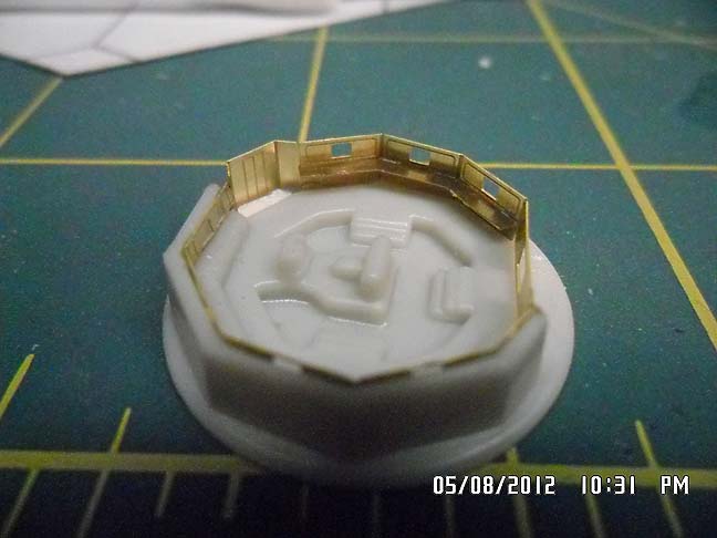
Then it was time to paint! Yay! That's the fun part. Well, in this case, it's also the most frustrating part. Imagine you've just built the AMT Enterprise bridge set and now you're going to paint it, but to make things challenging, you have to paint it from across the room looking through binoculars, using a long-handled brush so big you could paint the captain's chair with one stroke. I used various colors I had in stock, including Polly Scale RLM 65 for the chairs (like most hobby paints, it's not faithful to the Luftwaffe color, but it's about perfect here).

There's still need for touch-up and a bit more detailing, then it's time to add figures. I have a fret of Gold Medal Models 1/700 scale sailors that you may have spotted lying next to the bridge in previous posts. Some of them will be bent into seated positions and others left standing, then they'll get their Starfleet uniforms painted on and get superglued in place.

Friday, May 18, 2012

Tiny Enterprise Bridge Gets Eentsy Weentsy Chairs, or PGMS Cutaway Starship Photo-etch Set, Part 4

All right, I've done it! Since last time, I made ten Burke chairs at approximately 1/700 scale (to go with the PE figures that will also be on the Cutaway Enterprise bridge, chosen to match the height of the turbolift door). And they're installed. Once they're carefully painted, Lts. Uhura and Sulu, Ens. Chekov, and Mr. Spock will all have places to sit. (Ever notice Scotty doesn't sit much when he's on the bridge? That guy has ants in his pants!) This pic makes me notice something, though. That captain's chair looks like a loveseat! ("Yeoman Rand! Report to the bridge, and bring some Saurian brandy!")


Friday, May 11, 2012

PGMS Cutaway Starship Photo-etch Set, Part 3

(Previously on PGMS Cutaway etc.)

Tonight's episode: Adding handrails

Note: I should mention that the handrails are not part of the ParaGraphix photoetch set.

One of the distinctive features of the Enterprise bridge is the handrail around the center well. I couldn't very well make this tiny bridge (under one inch in diameter!) without adding the handrail. The first step was to drill holes for the stanchions. I used a pin vise with a #75 drill bit, that being the smallest bit I still have for the pin vise. (Tiny bits break so easily. I really need to get a new #61-80 set.) Here are the holes. Not perfectly positioned, but all the while I was thinking about how to do this better. I could rig up a rotary vise and a fixture to hold the pin vise so all the holes are equidistant from the center and at the same angle.

The next job was to thread wire through the holes to form the stanchions. First I tried a piece of steel wire I found in the drawer, but it was very hard to cut and there wasn't enough anyway. I think the wire was the remains of a #76 drill bit. Then I switched to using fine strands of copper wire I stripped out of some old speaker wire. I fed them in through the bottom and tried to get each one to come out the same length before bending the excess length over and supergluing it to the bottom. This wasn't too hard; again, I could do it better by precisely controlling the length of wire protruding through the floor. One way I thought of was painting the desired length on the end of the wire to mark it. It was also necessary to make all the stanchions stand at the right angle--they are angled in a bit.

Last was the trickiest part. I had to cut four handrails to length, bend them into shape, put a droplet of superglue on top of each stanchion, and somehow pick up the piece of handrail and position it. I ended up losing 3 or 4 pieces of handrail, and immediately set to work each time fabricating a replacement, as there was no point in looking for anything that tiny. I used pointy tweezers to pick up the handrails and had to lick the tweezers or the parts would disappear almost as soon as they were picked up.

Finally, I got all the handrails in place. It took a bit of patience and definitely made me think of ways to get better results.
Next time I think I'll be making a bunch of tiny Burke chairs.

Thursday, May 10, 2012

Prosthetic Made Entirely with Modeling Supplies

Back in January, I injured my thumb with a power drill while driving in drywall screws. It takes nails a heck of a long time to grow out and heal up, and for a while I've had this piece of thumbnail that keeps getting caught on things. That doesn't feel good, but it would really hurt if it got caught forcefully and did more damage to the nail. Until recently, all I needed to do was keep putting superglue in there (sometimes with accelerator).

Now it's grown out enough that just supergluing it won't work. Here's my prosthesis. It's sort of like fake nails they put on in a salon.

Here's how I made it. First, I put a rubber glove on that hand. I used a heat gun to soften a piece of sheet styrene and smash-molded it over the thumb. The heat of the plastic smarted even with the glove on.

I cut out the thumbnail shaped piece of styrene, superglued it to my thumb, filed it, and painted it with a mix of Model Master enamels: Panzer Interior Buff and RLM 23 red. Now part of me is a model.

Wednesday, May 9, 2012

PGMS Cutaway Starship Photo-etch Set, Part 2


Okay, as promised I worked on the Cutaway Enterprise bridge within 48 hours of my last post. (Actually, I promised to try. And did it anyway. Take that, Yoda!) Here are some pics of where this project stands right now. To find out how it got to this point..

Monday, May 7, 2012

PGMS Cutaway Starship Photo-etch Set, Part 1

Guess what just came in the mail? The new photo-etch set from ParaGrafix Modeling Systems for the AMT cutaway Enterprise (AMT kit 8790)! I got it for free, not 'cause I'm some modeling whiz, but because I won a contest on the Starship Modeler forum. To be nice, I thought I'd show it off so you can consider if you want to get one. Here's what you get:

You get a nice crisp sheet of brass photoetched parts about 4.2" X 5.7", along with a clearly illustrated instruction sheet (printed both sides) with references to the AMT kit parts that the photoetched parts augment or replace. The set comprises parts for the buzzard collector rotors (suitable for motorization), grilles for the inner sides of the warp nacelles and for the upper sides of the warp pylons, the grilles for the sides of the secondary hull on either side of the navigational deflector housing, the bussard collector clamps (those little details, three of which ring the bussard collector dome on the front of each warp nacelle), the rear face of the impulse engine, and a detailing set for the bridge (part 26 in the AMT kit). The parts for the bridge include a replacement for the upper panels around the starboard side of the bridge and a replacement for the missing wall around the port side of the bridge. This includes everything from the turbolift to the main viewer, with consoles.

This is what part 26 looks like on the tree, right next to the port nacelle. You can see there's a whole side missing. Maybe you can't tell, but the captain's chair and the navigation/helm console is there, in the center well. Pretty basic.

I'll be working on just the bridge for an upcoming post. Hopefully, it will be up in the next 48 hours.

Saturday, May 5, 2012

Round 2 Klingon Bird of Prey WIP, Part 3

There's just a bit of progress to report on both fronts since the last post. First the model kit.

Dremel with carbide bit (left),
pin vises, files, knives, pin vise.
I was hollowing out the windows and the slots around the photon torpedo launcher (and navigational deflector?). I started with drilling a series of holes using bits from my #61-80 set in my pin vise. Fine work like this (for someone at my age with presbyopia) is best done with a jeweler's loupe. Since this lets me focus about three inches away from my eye, it works pretty well to steady the end of the pin vise against my forehead or chin. Then I milled out the holes using the dremel at its lowest speed with micro size carbide bits that have a 1/8" shank, so they fit in a collet. (No mini chuck! Those things aren't totally useless, I guess, but they always have a bit of wobble, no good with tiny drill bits.) Square and triangular files and a #11
blade were useful for cleaning up the holes. The windows come in pairs, with a narrow bar between them, and I ruined the bar between the pair of windows on the port side of the bridge. No matter, it can be fixed with sheet styrene.
Bridge, port side.
Starboard side

The filigree around the torpedo launcher/main deflector.