
If you followed the discussion on SSM forum about this, you know this has been a long time in the works. Pat Suwalski of
Tetryon Parts shared his progress as he worked to accurize the back side of the neck (aka battlehead) of the AMT 1:1400 Enterprise D, now re-released in clear styrene. He pointed out what was wrong with it and showed how he was fixing it to match the real thing--the large filming miniature. One problem was that the impulse engine was in the wrong place. However, this is not just about his correcting other people's mistakes, something everyone wants to do, but correcting his own, which few people want to do.
 |
| Old upgrade part test-fit. |
Finally, June 29 he offered the piece for sale. I ordered one immediately, in clear resin with matching decals (it's available in opaque resin as well, and decals are optional). I've got the clear kit, and plan to use the kit's aztec decals. The kit decals (
art by Jim Small of EIMB) are made to fit the kit, so if you correct an inaccuracy, you'll need a corrected decal as well!
It arrived in the mail July 17. I got out the 1701D kit and assembled the sides of the neck (parts 5 & 6) to test fit the replacement part. (Note: the part replaces the back of part 3, which is the back of the neck and top of the battle head, or the mating surface to the saucer section.) Pat had been candid in his posts on SSM forum (
here's the thread) about the fact that his part was thin and might warp. Well, it did. Mostly I think the part was squashed flat in the mail, since it was shipped in a padded envelope. The part has a boxlike structure on the inside of the impulse engine, and that was crushed, though it could be rebuilt easily with sheet styrene. The worst problem, though it was the most subtle, was a wavy distortion of the area where the neck blends to match the curve of the saucer, most pronounced above shuttlebay 2. I wasn't sure I could fix that as easily.
 |
| Old (top) and improved upgrade parts. |
 |
| New upgrade part test-fit. |
I emailed Pat immediately and he said he'd send a replacement part. Actually, I hadn't even asked for one, just asked about softening it in hot water to make it plastic enough to form back into shape. The new part arrived today (July 30), and comparing them side by side, you can see the new part has a deep curve to it and the old part is pretty flat. It's also twice as thick: according to my digital caliper, about .110-.120", as opposed to .550-.650" on the old one. The impulse engine box came through the mail okay, and I could see no wavy distortion in the part.I test fit the new part to the back of the neck, and found it was slightly flattened by its trip through the mail (it also came in a padded envelope), but to a much lesser degree, and that it conforms to the shape of the neck with a little finger pressure. I will put this part in hot water anyway, simply to soften it up so it won't want to spring back when bent. I more than suspect that Pat is working on this part or the packaging to eliminate even this little problem.
 |
| New upgrade part test-fit. |
So much for this peek at Tetryon Parts Enterprise D Upgrade. Sorry if you were expecting to see a build this time, but I look forward to building the clear Enterprise D in the near future, lit of course, and putting this part to good use, and there will be a series of WIP posts then.
And I can definitely recommend Tetryon Parts after this experience.
PS: July 31, 2012.
Now my part is perfect!
I dipped the part in boiling hot water for a minute, draped it over the other neck parts holding it in place with my fingers, then dipped the whole assembly into icewater. The clear resin is floppy like a sheet of rubber at 212 F. I'd recommend not getting the water that hot--maybe just the temperature of hot bathwater.
The flattening of the part wasn't too bad in the first place--it would have stayed in place with CA or epoxy--I just wanted to assemble it without putting any stress on it.


 It needed some kind of dome, so I scavenged a piece off some old blinds. It's clear, so I can add lighting effects inside it. I also added Evergreen channel to the sides. It looks like rails that the warp core would slide in and out on for installation and removal. (Or emergency jettisoning! Whee!) There's a beveled edge in the passageway so I cut a little off the warp core so it can sit in place. I also cut slots in the side walls for the channel on the sides of the core to fit in. I forgot to take a picture of the warp core installed. Well, it fits and next time there will be a pic of that. Plus cleanup of the slots and a whole lot of detailing. Klingon warp cores must have enough plumbing all over them that they look like a plate of spaghetti. And the whole interior of the landing gear bay and entryway needs gobs of detail, too. Some of this will come next time.


 My 13 year old daughter Sylvia isn't too much into model building. Or at all. But she is into Doctor Who, and (everyone get ready to say, "Awww!") spending time doing stuff with her daddy. I'd mentioned to her we could build a model of the Tardis out of popsicle sticks, based on drawings from the internet, and she was into it. In fact, she built her own Tardis out of Legos. Here it is, along with a figure of the 11th Doctor she made from a clothes pin. Adorable, huh?
 The first step was research, and we found a suitable drawing of the Tardis from 2005 onwards. (The 10th Doctor is her first Doctor, so this Tardis looks right to her. Besides, it looks better to me, too, and more like a real police box than any since the original.) Here's the link. There's a side view, too, but it only differs in the lack of door detail. We printed it out full size, and it was 10 inches tall, representing the 10-foot Tardis at 1/12 scale. We decided to cut the size in half because of the length of a popsicle stick. Printing the drawing at exactly one-half normal size involved experimenting with the printer setup until we tricked the printer into doing what we wanted.
 Once we had the drawing, we had to figure out what part to make first and how to do it, and take measurements from the drawing. It seemed logical to build from the bottom up, so we measured the width and thickness of the base in the drawing. We also measured the popicle sticks. Sylvia measured with an engineer's scale ruled in tenths of an inch, a machinist's pocket rule with 1/32nds and 1/64ths, and a digital caliper. She had used ordinary rulers of course, but none of these. She also ended up getting a refresher on fractions and decimals and long division, and an introduction to tolerances. It turns out that the dimensions of popsicle sticks vary rather more than you might expect, and Sylvia figured out why: tighter tolerances mean higher cost, and popsicle sticks must be cheap to make! The base was two and a fraction popsicle sticks thick, so as a compromise solution, we decided to make the base two sticks thick, with the sticks laid crosswise. The width of the base was 6-2/3 times the width of an average stick, and we didn't compromise here: a popsicle stick had to be cut lengthwise

 If you followed the discussion on SSM forum about this, you know this has been a long time in the works. Pat Suwalski of Tetryon Parts shared his progress as he worked to accurize the back side of the neck (aka battlehead) of the AMT 1:1400 Enterprise D, now re-released in clear styrene. He pointed out what was wrong with it and showed how he was fixing it to match the real thing--the large filming miniature. One problem was that the impulse engine was in the wrong place. However, this is not just about his correcting other people's mistakes, something everyone wants to do, but correcting his own, which few people want to do.


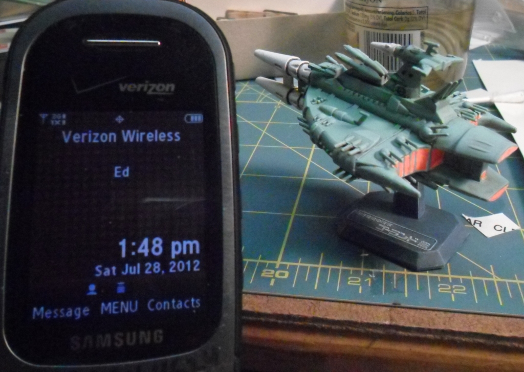


 Here's the victim for my current attempt: Bandai Star Blazers Mini No. 10, a Comet Empire missile ship. This sucker is just bristling with weaponry. I guess the Comet Empire is into massive overkill.

 Finished, as in I've had enough frustration and I've got other modeling projects I am impatient to get back to. That sounds disgruntled, but actually this was a pretty good learning experience. It was an impulsive mistake to paint the figures before bending them, and some of the paint came off. I had a little trouble bending the figures into the desired poses. In particular, the bend at the hips for a seated figure tended to come out too low. As a result, I have a better idea of how to get the bend to come out where I want it. Holding the figures with tweezers and dipping their feet in superglue worked pretty well, but I needed to be more patient about placing them. Amazingly, none of the ten figures were eaten by the carpet monster!