


 Okay, as promised I worked on the Cutaway Enterprise bridge within 48 hours of my last post. (Actually, I promised to try. And did it anyway. Take that, Yoda!) Here are some pics of where this project stands right now. To find out how it got to this point..
I've used photoetch details before, but so infrequently you can call me a newbie. That means this little exercise could be a sort of Photoetch for Dummies. I started by following directions, sort of. I didn't feel like looking for a tile or piece of glass to cut out the photoetch on, so I cut it on my wooden workbench using an X-acto knife. It really is better to cut on an inflexible surface. Why? Imagine using a sofa cushion as a surface on which to cut sheet styrene (aka plasticard). Even though the wood is a pretty firm surface, the photoetch did bend a tiny bit, though you only notice it through a magnifier or in a macro photograph. (Guess what: here come macro photographs!)


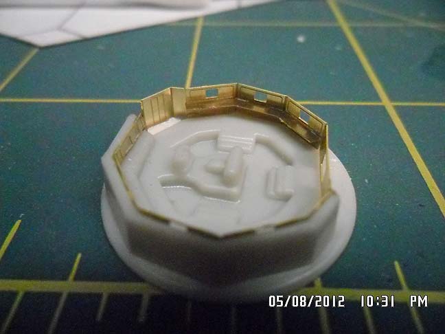
I cut out the upper panel around the starboard side of the bridge first, then test fit it and fastened it with superglue gel. I also used accelerator, once I had it tightly in place. What I noticed after putting it in is that this surface on the kit part isn't vertical--it's tilted back. (This shouldn't be any surprise, since in injection molding there's always a draft angle for ease of ejection of parts from the mold. Also, get a load of that kit part. It looks like it's carved out of soap! You'd really expect that sort of accuracy?) The photoetch part is made to be vertical, like the real display panels around the Enterprise bridge. As a result, there's a gap behind the photoetch at the top.The PGMS instructions actually suggest cutting away the upper part of the kit part if you want the displays to be lit from behind. Even without lighting, here's what I'd do if I had it to do over: cut away the upper panel on the kit part and attach the photoetch part to some sheet styrene, then cement that to the kit part. Live and learn.
The remaining two photoetch parts for the bridge were next. These are the wall around the port side, including the turbolift doors and the main viewer, and the console around this side. It seemed like life would be easier assembling these and then installing them. I noticed the raised floor around the perimeter of the bridge doesn't extend into the shallow alcove where the turbolift is set back a couple feet. I didn't want a step down into the turbolift, so I measured the thickness and found I could fix this by cutting out a tiny trapezoid from .040" sheet styrene. This I cemented in place on the kit part after test fitting it into the photoetch. Next I tried supergluing this assembly in place, but had a bit of trouble. It got stuck before it was in position. I think the problem was residual accelerator. I removed it and scraped away the bits of superglue, then gave the bridge a really good rinse. Then I fit it into place, applying a little superglue gel from the back, starting at the ends and working toward the middle. This time it fit pretty well.
Next time: Adding handrails.
Howdy, just stopping by to see what is new.
ReplyDeleteThese are some nice looking PE set for the Enterprise :D
Thanks for stopping by. I am definitely finding out the had way how best to use these PE parts for the bridge. The final post about this will have a list of my recommendations (so you don't have to repeat my mistakes).
ReplyDeleteThat looks very nice. Good luck with it ;)
ReplyDeleteRegards
moviekits.net